Honors + AP: Acoustics - Sound, Resonance, and Wave Interactions
This unit extends the waves and sound portion of the Waves and Radiation page. Students use sound as a physical wave system to investigate reflection, Doppler shift, shock waves, interference, beats, standing waves, and resonance in closed pipes.
Unit Question: How can sound reveal the behavior of waves that cannot easily be seen?
NGSS Standards Alignment
This acoustics unit is built around the high school NGSS wave standards. The strongest match is HS-PS4-1, because students use mathematical relationships among wave speed, wavelength, and frequency for sound waves in air. The inquiry lab also supports HS-PS4-5 when students communicate how wave behavior is used in devices such as sonar, ultrasound, microphones, and musical instruments.
HS-PS4-1
Use mathematical representations to support a claim about relationships among frequency, wavelength, and speed of waves traveling in various media.
HS-PS4-5
Communicate technical information about how devices use wave behavior and wave interactions with matter to transmit and capture information and energy.
HS-PS4-2
Evaluate questions about information transmission. This is a secondary connection through microphones, ultrasound, sonar, and audio recording technology.
HS-PS4 Topic Arrangement
Wave properties, information technologies, instrumentation, and applications of wave interactions.
Science and Engineering Practices
- SEP Using Mathematics and Computational Thinking: Students use \(v=f\lambda\), echo timing, Doppler equations, and percent error.
- SEP Planning and Carrying Out Investigations: Students collect resonance data from a closed-pipe air column.
- SEP Analyzing and Interpreting Data: Students identify resonance lengths and use them to calculate wavelength and wave speed.
- SEP Obtaining, Evaluating, and Communicating Information: Students explain how acoustic technologies use wave behavior.
Disciplinary Core Ideas
- DCI PS4.A Wave Properties: Wavelength, frequency, speed, reflection, interference, resonance, and wave superposition.
- DCI PS4.C Information Technologies and Instrumentation: Sonar, ultrasound, microphones, speakers, and musical instruments.
Crosscutting Concepts
- CCC Patterns: Harmonic frequencies, resonance lengths, and beat frequency patterns.
- CCC Cause and Effect: Changes in motion, path length, and boundary conditions cause observable sound effects.
- CCC Systems and System Models: Pipes, strings, air columns, and listening environments are modeled as interacting wave systems.
Foundations of Sound and Acoustics
HS-PS4-1 HS-PS4-5 Using Math PS4.A Patterns
Sound is a mechanical longitudinal wave. It requires a medium such as air, water, metal, or another material. In air, sound travels as repeating regions of compression and rarefaction. The air molecules do not travel all the way from the source to your ear; instead, energy is transferred through local vibrations of the medium.
Frequency
The number of vibrations per second. Frequency is measured in hertz, \(\text{Hz}\), and is related to pitch.
Wavelength
The distance between repeating parts of a wave, such as compression to compression.
Amplitude
The size of the pressure variation. Larger amplitude usually means louder sound.
Speed of Sound
The speed depends on the medium and temperature. At room temperature in air, a common estimate is \(343\ \text{m/s}\).
Show Solution
Show Solution
Echoes and Reflection of Sound
HS-PS4-1 HS-PS4-5 Using Math PS4.A / PS4.C Cause & Effect
An echo occurs when sound reflects from a surface and returns to the listener after a noticeable delay. Echoes connect wave reflection to real technologies such as sonar, ultrasound imaging, and echolocation.
The factor of \(2\) appears because the measured time usually includes the trip from the source to the reflecting surface and back to the listener.
Show Solution
Show Solution
The Doppler Effect
HS-PS4-1 HS-PS4-5 Developing Models PS4.A / PS4.C Cause & Effect
The Doppler effect is the apparent change in frequency caused by relative motion between a wave source and an observer. When a source moves toward an observer, wavefronts are compressed and the observed frequency is higher. When the source moves away, wavefronts are stretched and the observed frequency is lower.
For a stationary observer and a moving source, a useful classroom form is:
Show Solution
Show Solution
Sonic Booms and Shock Waves
HS-PS4-1 Developing Models PS4.A Patterns
A sonic boom forms when an object travels faster than sound through a medium. The object outruns its own pressure waves, causing wavefronts to pile up into a shock wave. A common misconception is that the boom happens only at the instant the object breaks the sound barrier. In reality, a supersonic object continuously creates a shock wave as it travels.
Show Solution
Show Solution
Interference and Superposition
HS-PS4-1 HS-PS4-5 Analyzing Data PS4.A / PS4.C Systems & Models
Interference occurs when waves overlap. The displacement or pressure variation at a point is the sum of the individual wave effects. This is called superposition.
Constructive Interference
Waves arrive in phase and reinforce each other.
Destructive Interference
Waves arrive out of phase and reduce or cancel each other.
Show Solution
Show Solution
Beat Frequencies
HS-PS4-1 Using Math PS4.A Patterns
Beat frequencies occur when two waves with nearly equal frequencies interfere. The listener hears a single tone that gets louder and softer at a steady rate. Musicians use beats to tune instruments: as the two frequencies become closer, the beat frequency becomes slower.
Show Solution
Show Solution
Standing Waves and Resonance
HS-PS4-1 HS-PS4-5 Developing Models PS4.A / PS4.C Systems & Models
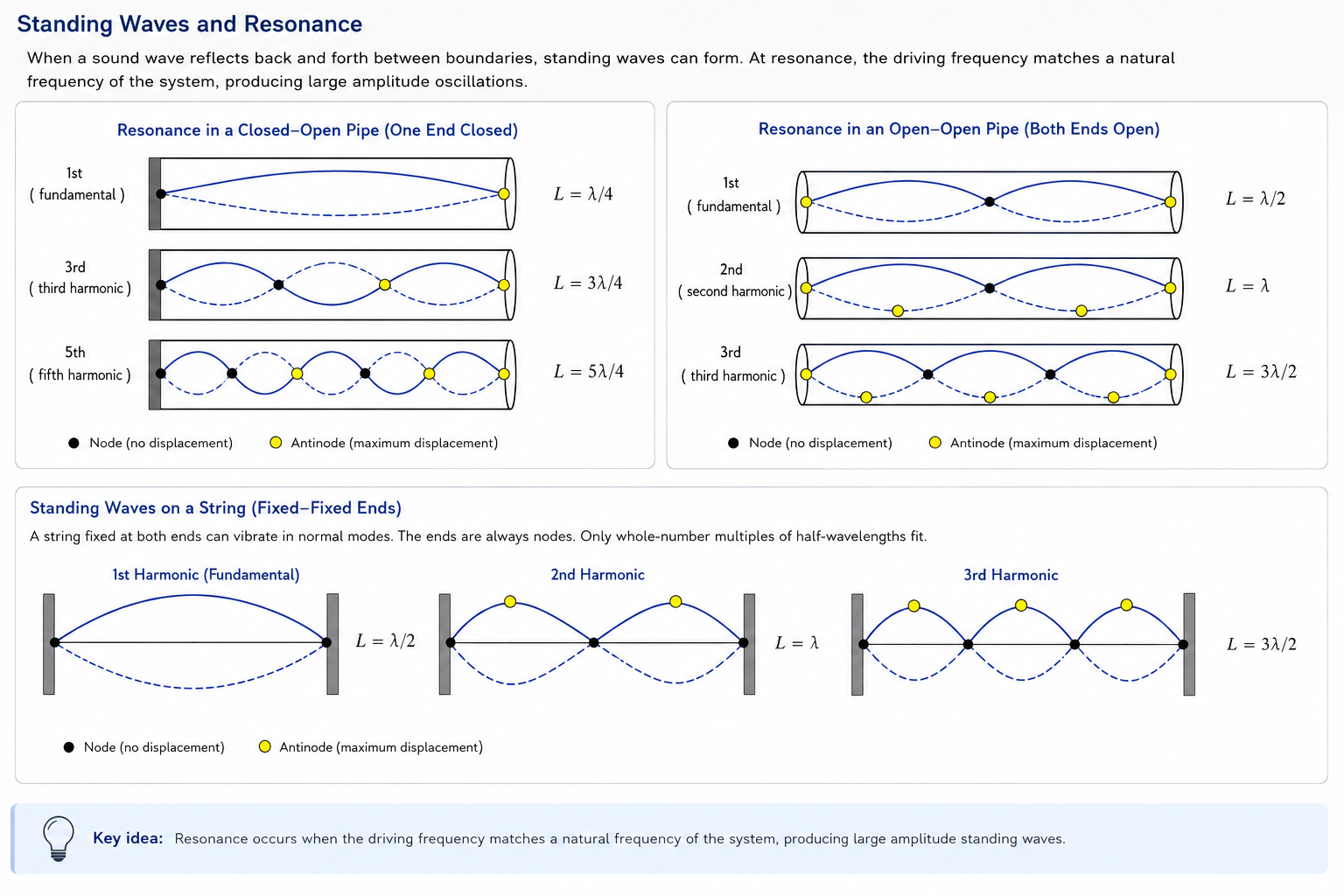
A standing wave forms when waves reflect and interfere in a stable pattern. In sound systems, resonance occurs when a driving frequency matches one of the natural standing-wave patterns of the system. At resonance, sound becomes much louder because energy is transferred efficiently into the oscillation.
Open End
An open end of an air column behaves like a displacement antinode and pressure node.
Closed End
A closed end behaves like a displacement node and pressure antinode.
Successive resonance lengths in a closed pipe are separated by half a wavelength:
Show Solution
Why Harmonics and Resonance Exist
HS-PS4-1 HS-PS4-5 Developing Models PS4.A Patterns Cause & Effect
Every physical system that supports waves has boundary conditions—constraints at the edges that dictate how the wave must behave at those points. Boundary conditions are the fundamental reason that only certain wavelengths and frequencies can sustain themselves inside a system. A wave that does not satisfy its boundary conditions will destructively interfere with itself and die out. A wave that does satisfy them will constructively reinforce with each reflection, growing into a large, stable oscillation called a standing wave. The set of frequencies that produce standing waves are the system's harmonics, and the amplification that occurs when a driving force matches one of those frequencies is resonance.
Boundary Conditions: The Origin of Harmonics
Consider a wave bouncing back and forth inside a confined system. Each time it reflects, it overlaps with incoming waves. For most frequencies the reflected and incoming waves are out of step and cancel. But at specific frequencies, the round-trip path length is an exact number of half-wavelengths, so the reflections line up perfectly and produce standing waves. The pattern at the boundaries determines which set of harmonics is allowed:
Pipes (Air Columns)
A closed end forces a displacement node; an open end forces a displacement antinode. A pipe closed at one end supports only odd-numbered harmonics because only odd multiples of a quarter wavelength fit those mixed boundary conditions. A pipe open at both ends supports all harmonics because identical boundary conditions at each end allow both even and odd multiples of a half wavelength.
Strings
Both ends of a string are fixed, creating nodes at each end. The string must fit an integer number of half-wavelengths between its endpoints. This means all harmonics are possible: the fundamental is one half-wavelength, the second harmonic is two half-wavelengths, and so on. The frequency of each harmonic is an integer multiple of the fundamental.
Architecture
A room or concert hall is a three-dimensional resonant system. Sound reflects between walls, floor, and ceiling, creating room modes—standing wave patterns at specific frequencies determined by the room's dimensions. Architects design concert halls to spread these modes evenly and add absorptive materials so no single frequency dominates, avoiding the muddy reverberation that comes from strong resonance at a few frequencies.
Why Resonance Amplifies Sound
Resonance is not a new source of energy—it is efficient energy transfer. When a driving force vibrates at the same frequency as a natural mode of the system, each push arrives exactly in phase with the existing oscillation. The amplitude grows with every cycle, like pushing a swing at just the right moment. At any other frequency, the pushes are sometimes in phase and sometimes out of phase, so the oscillation stays small. This is why a tuning fork held over a pipe at the right length produces a dramatic increase in loudness, and why a singer sustaining the right pitch can set a wine glass vibrating until it shatters.
Resonance in Architecture
The physics of resonance extends directly into the built environment. Every enclosed space has a set of resonant frequencies called room modes, determined by the distances between opposing surfaces. For a rectangular room the lowest mode along a single dimension has a half-wavelength equal to that dimension's length:
A small practice room with one wall 3.4 m away from the opposite wall has a first mode near 50 Hz—a low bass frequency that booms and muddies the sound. Concert hall designers combat this by using non-parallel walls, diffusive surfaces, and absorptive panels at calculated positions to break up strong standing-wave patterns. The Elbphilharmonie in Hamburg, for example, uses algorithmically carved wall panels to scatter sound in thousands of directions, preventing any single room mode from dominating.
Problematic Resonance
The Tacoma Narrows Bridge (1940) collapsed when wind excited a torsional resonance mode. Soldiers break step crossing footbridges to avoid driving a resonance at the bridge's natural frequency. Tall buildings sway in wind gusts that happen to match a structural mode.
Designed Resonance
Organ pipes, guitar bodies, and wind instruments are deliberately built to resonate at useful frequencies. A violin body amplifies the strings' vibrations by resonating over a broad range. Whispering galleries in domed buildings focus sound along curved surfaces using constructive interference of reflections.
Show Solution
Show Solution
Harmonics in Pipes
HS-PS4-1 HS-PS4-5 Using Math Developing Models PS4.A / PS4.C Patterns
A pipe supports standing waves at specific frequencies determined by its length and whether each end is open or closed. The lowest allowed frequency is the fundamental (first harmonic). Higher harmonics are integer multiples of the fundamental that also satisfy the boundary conditions. The full set of harmonics gives an instrument its timbre—a clarinet (effectively a closed pipe) sounds different from a flute (effectively an open pipe) because they emphasize different harmonics.
Open Pipe (Open at Both Ends)
Both ends are displacement antinodes. The fundamental fits one half-wavelength into the pipe length. All integer harmonics are present.
Closed Pipe (Closed at One End)
The closed end is a displacement node and the open end is a displacement antinode. The fundamental fits one quarter-wavelength into the pipe. Only odd harmonics are present because only odd multiples of a quarter wavelength satisfy these mixed boundary conditions.
Comparing Open and Closed Pipes
| Property | Open Pipe | Closed Pipe |
|---|---|---|
| Boundary conditions | Antinode at both ends | Node at closed end, antinode at open end |
| Fundamental wavelength | \(\lambda_1 = 2L\) | \(\lambda_1 = 4L\) |
| Fundamental frequency | \(f_1 = v/(2L)\) | \(f_1 = v/(4L)\) |
| Harmonics present | All: \(f_1, 2f_1, 3f_1, \dots\) | Odd only: \(f_1, 3f_1, 5f_1, \dots\) |
| Instrument examples | Flute, organ pipe (open) | Clarinet, bottle, closed organ pipe |
Show Solution
Show Solution
Show Solution
Show Solution
Harmonics on Strings
HS-PS4-1 HS-PS4-5 Using Math Developing Models PS4.A / PS4.C Patterns Cause & Effect
A vibrating string fixed at both ends is one of the clearest examples of harmonic behavior. Because both endpoints are fixed, they must be displacement nodes. The string must therefore fit an integer number of half-wavelengths between its endpoints. The lowest frequency that satisfies this condition is the fundamental (first harmonic), and every higher harmonic adds one more half-wavelength loop to the pattern.
The Harmonic Series on a String
Here \(L\) is the string length, \(v\) is the wave speed on the string, \(T\) is the tension, and \(\mu\) is the linear mass density (mass per unit length, in kg/m). The wave speed on a string is \(v = \sqrt{T/\mu}\).
Wavelength Pattern
The wavelength of the \(n\)-th harmonic is: \[\lambda_n = \frac{2L}{n}\] As the harmonic number increases, the wavelength gets shorter and the frequency gets higher.
What Controls Pitch?
A string's fundamental frequency depends on three things: length (shorter = higher pitch), tension (tighter = higher pitch), and mass density (thinner/lighter = higher pitch). Musicians use all three: pressing a fret shortens the string, tuning pegs change tension, and different strings have different thicknesses.
Illustrated Harmonic Modes
The diagrams below show the displacement pattern for each harmonic on a string of length \(L\). Nodes (points of zero displacement) are shown in green and antinodes (points of maximum displacement) are shown in gold. The dashed line shows the equilibrium position of the string.
Harmonic Summary Table
| Harmonic \(n\) | Loops | Nodes | Antinodes | Wavelength \(\lambda_n\) | Frequency \(f_n\) |
|---|---|---|---|---|---|
| 1 (fundamental) | 1 | 2 | 1 | \(2L\) | \(f_1\) |
| 2 | 2 | 3 | 2 | \(L\) | \(2f_1\) |
| 3 | 3 | 4 | 3 | \(2L/3\) | \(3f_1\) |
| 4 | 4 | 5 | 4 | \(L/2\) | \(4f_1\) |
| \(n\) | \(n\) | \(n+1\) | \(n\) | \(2L/n\) | \(nf_1\) |
Factors That Affect String Frequency
Musical Connections
When a guitar string vibrates, it does not produce just one frequency. It vibrates simultaneously in its fundamental and many overtones. The relative strength of each harmonic is what gives the instrument its characteristic timbre. Lightly touching the string at its midpoint while plucking damps the fundamental and odd harmonics, forcing the string to vibrate at the second harmonic—the familiar "harmonic" technique that guitarists and violinists use. Touching at the one-third point isolates the third harmonic, and so on. The note's pitch jumps up by an octave (2nd harmonic), an octave plus a fifth (3rd), two octaves (4th), etc.
Sample Questions
Show Solution
Show Solution
Show Solution
Show Solution
Show Solution
Show Solution
Show Solution
Show Solution
Show Solution
Inquiry Lab: Measuring the Speed of Sound with a Closed Pipe
HS-PS4-1 HS-PS4-5 Planning Investigations Analyzing Data PS4.A / PS4.C Patterns
Essential Question: How can resonance in an air column be used to determine wavelength and measure the speed of sound?
Materials
- Resonance tube or clear graduated tube
- Water reservoir or tall cylinder partially filled with water
- Known tuning fork, such as \(256\ \text{Hz}\), \(512\ \text{Hz}\), or another assigned frequency
- Rubber striker or soft tuning fork mallet
- Meter stick or measuring tape
- Thermometer, if available
- Data table and calculator
Safety and Setup
- Do not strike tuning forks on lab tables or hard metal surfaces.
- Keep water away from electrical devices and outlets.
- Keep the tuning fork above the tube opening; do not hit the glass or plastic tube.
- Work quietly enough to hear resonance clearly.
Investigation Procedure
- Predict: Use \(v=f\lambda\) and \(v\approx343\ \text{m/s}\) to estimate the wavelength for your tuning fork.
- Predict the first resonance: Estimate \(L_1\approx\lambda/4\).
- Create the closed pipe: Raise or lower the water level so the air column above the water changes length. The water surface acts like the closed end.
- Strike the tuning fork: Hold it near the tube opening without touching the tube.
- Find resonance: Slowly change the air column length until the sound becomes noticeably louder.
- Record \(L_1\): Measure the air column length from the water surface to the open end of the tube.
- Find \(L_2\): Continue changing the air column length until the next loud resonance occurs.
- Calculate wavelength: Use \(L_2-L_1=\lambda/2\), so \(\lambda=2(L_2-L_1)\).
- Calculate speed: Use \(v=f\lambda\).
- Evaluate: Compare your result to the accepted value and identify likely sources of error.
Data Table
| Trial | Tuning Fork Frequency \(f\) | First Resonance \(L_1\) | Second Resonance \(L_2\) | \(\lambda=2(L_2-L_1)\) | \(v=f\lambda\) |
|---|---|---|---|---|---|
| 1 | |||||
| 2 | |||||
| 3 |
Analysis Questions
- Why does the sound become louder at resonance?
- Why is the water surface treated as the closed end of the pipe?
- Why is using \(L_2-L_1\) often better than using only \(L_1\)?
- What would happen to the resonance lengths if you used a higher-frequency tuning fork?
- How would a warmer classroom affect the speed of sound?
- What sources of error could make your measured speed too high or too low?
Sample Calculation
Show Solution
Conclusion Claim
Write a paragraph using the claim-evidence-reasoning format:
- Claim: State your measured speed of sound.
- Evidence: Use your resonance lengths, calculated wavelength, and frequency.
- Reasoning: Explain why resonance in a closed pipe allowed you to determine wavelength and speed.
Engineering Extension: Design a Simple Wind Instrument
HS-PS4-1 HS-PS4-5 Constructing Explanations Communicating Information PS4.A / PS4.C Systems & Models
Design Challenge: Use wave speed, frequency, wavelength, and boundary conditions to design a simple wind instrument that produces a target frequency.
Design Constraints
- Your instrument must produce at least one measurable target frequency.
- You must explain whether it behaves more like an open pipe or a closed pipe.
- You must calculate the expected length before testing.
- You must test the sound using a tuner app, frequency analyzer, or classroom sensor.
- You must revise your design based on evidence.
Deliverables
Design Sketch
Include dimensions, open/closed ends, and where the sound is produced.
Physics Calculation
Show how frequency, wavelength, and pipe length are related.
Test Data
Record the target frequency, measured frequency, and percent error.
Revision Explanation
Explain how your design changed and why.
Rubric
| Score | Description |
|---|---|
| 1 | Design is attempted but wave behavior is not clearly connected to the instrument. |
| 2 | Design produces sound, but calculations or explanations are incomplete. |
| 3 | Design uses relevant wave equations and includes basic testing. |
| 4 | Design, calculations, measurements, and explanations are accurate and clearly connected. |
| 5 | Design includes thoughtful revision, strong evidence, and a clear explanation of boundary conditions and resonance. |